OTOH is a hardware interface for manual beat slicing of audio samples.
Why this project
I wanted to create a plug-and-play instrument that would free up the producer from programming a machine and allow them to manipulate the sample with their hands.
-
The technique of slicing a beat into small pieces and then rearranging them to create new beats has shaped the music industry since the 70s. New technologies allowed to make it easier and more affordable, but at the time this project started (2008) the industry had never explored interfaces that go beyond a grid of buttons or computer software. In addition to that, a certain degree of setup and editing was always necessary, which almost sounds (pun intended) contradictory to the analog qualities that often these processed beats carry with them. There was no, plug and play, but rather, plug sit down, edit, program, have-the-machine-play — especially in the case of drum and bass.
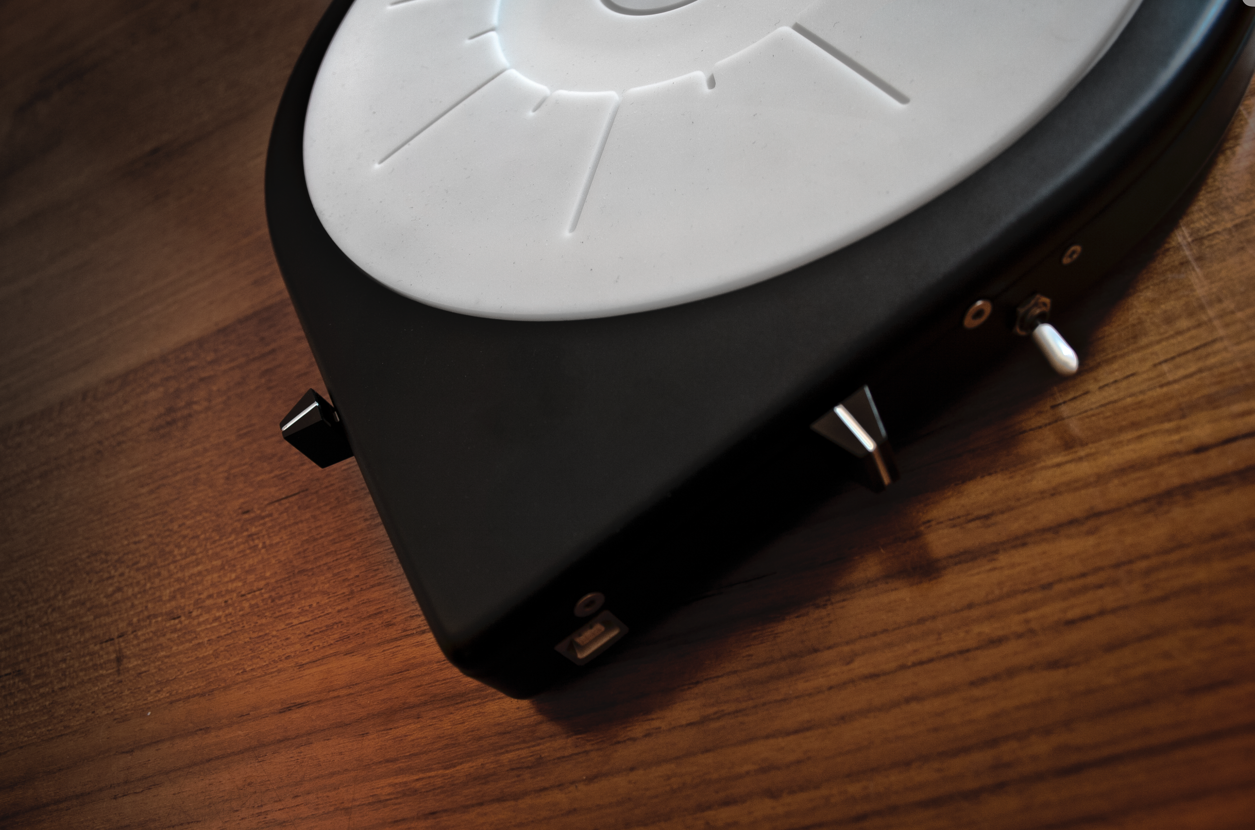
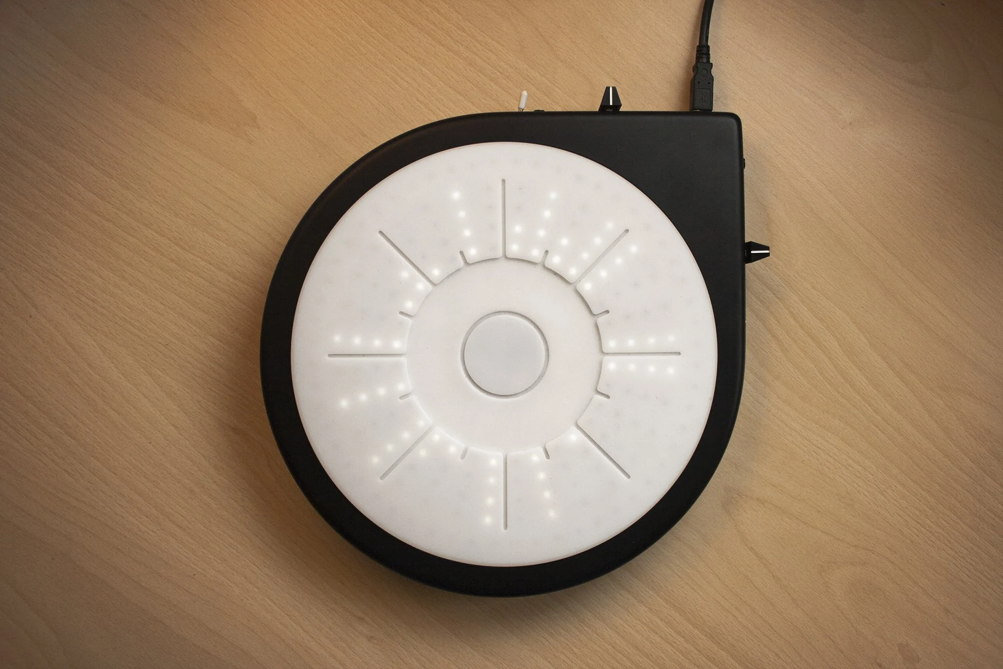
The two faders are used for volume control and for a stuttering effect. I manage to make the latter spring loaded so it would cancel the effect upon release without having to manually move it to 0 position. Lastly, the switch allows to quickly change playback direction.
Interface design — Interfacing with sound
The goal for the interface design was to create an instrument that would provide a feeling as close as possible to manipulating and touching the actual audio sample.
So I started from exploring audio sample representations to use as a foundation of the instrument’s shape.
I approached the problem in the most basic way possible. I listed the most obvious properties of a sample such as beginning, end, length, or frequency, and sketched different visual representations for each of them. On parallel, I run a series of user testing using a rudimental prototype featuring some of the effects I had in mind. The prototype was designed with no distinct visual feature since my goal was to ask users what they feel and imagine when they heard a certain audio manipulation.
Fast forwarding the process, here is how I got to the basic circular representation of the audio sample:

If we take a drumbeat’s waveform, it may very much look something like this . I then divided the samples in 64 parts and assigned to each a value going form 0 to 7, based on the highest value of the waveform in each region.

What I ended up with had a strong horizontal symmetry. Keeping only the top was enough to distinguish the sample basic features. The result was a low-resolution representation of the waveform, enough to provide a visual clue to the performer on which piece was just being played.

The decision of giving it a circular shape was affected by the progress bar behavior when looping a part that starts towards the end of the sample and ends at its beginning. The image below shows how in a horizontal representation the looped region will cause the progress bar to jump between the end and beginning of the sample. On the right, the circular shape allows to loop the same region without the disturbing jump.

At this point the main feature of the hardware design was defined. The 90 degrees corner was introduced to be able to allocate sliders and other controllers, as well as a way to indicate where the sample beginning point is.


A close-up of the bottom side of the silicon pads. The small holes serve to channel the light form each LED in order to keep its projected dot sharp on the surface.
Hardware design
Turning this interface design into hardware was likely the most challenging and fun part. Here are some aspects of it.
Keyboard
In order to allow a comfortable performance, I wanted allow the player to press the pads without having to aim precisely. This required very big sensitive areas which conflicted with the need to have the light from the LEDs to pass through. The resulting design is visible below. The image shows one of the three layers required to make a keyboard and you can see how the LEDs matrix is placed underneath.
The circular strip that surrounds the keyboard is used to control a tape effect. Pressing it will slowly stop the sample similarly to putting a finger on a playing record or reel.

Printed Circuit Board
Since I had no experience with electronic engineering cad software I found myself more at ease using Illustrator to design the printed circuit board (PCB). The file was then converted into a format suitable for PCB printing. The image below shows one of the two sides of the board.
The PCB is then connected to an Arduino board as a big drop-shaped shield.

Enclosure
Producing the enclosure was the most expensive part. I certainly couldn’t afford injection molding so I designed it to be made by two thermoformed pieces I could then screw together with all the pieces inside (PCB, LEDs protection, keyboard and silicon pads) layered on top of each other.


A close-up of the printed circuit board. All components to process input and output had to be localized in the center in order to allocate all the possible space for the LEDs circular matrix.
OTOH today
In its brief existence OTOH has gained a decent fan base and the attention of a couple of companies in the music industry interested in producing it. I evaluated the possibility of producing and selling it myself but eventually none of these paths led to a public release.
In the process I certainly learned lessons on many fronts. If you are interested in learning more feel free to reach out and I’d be happy to share some story.
THANK YOU FOR VISITING
•
THANK YOU FOR VISITING •